CAD Guide V2 - How to create a CAD file for Deep Maps
We have created this document to assist you in delivering your CAD data (DWG; DXF) to Heidelberg Mobil. In order to ensure your CAD data can be successfully processed, it must meet certain quality requirements. This guide provides a quick, step-by-step process for creating suitable CAD data.
Step 1: Determine what the map will show
When you send us overloaded files, we need to understand your data first. This means that expenses can rise disproportionately. Therefore, take the time to think about what objects and areas should be on the map.
There can be for example:
booths
rooms
meeting rooms
facilities
special areas
etc.
Step 2: Create New Layers
In order to identify the necessary features, please add layers with the prefix HDMI_ to your CAD Plan. Each feature type must have at least two layers: the geometry and a number or text layer. A third layer could contain optional information, such as the text of the geometry.
Please use the following naming convention for layers:
Mandatory Layers:
Layer Content |
Layer Name |
|---|---|
Building outline |
HDMI_building_outline |
In case details such as aisles and corridors should appear on the map |
HDMI_building_detai |
Meeting room geometries |
HDMI_meetingrooms |
Text to appear as label on a meeting room |
HDMI_meetingrooms_text |
Number to appear as label on a meeting room |
HDMI_meetingrooms_number |
Booth geometries |
HDMI_booths |
Text to appear as label on a booth |
HDMI_booth_text |
Number to appear as label on a booth |
HDMI_booth_number |
Outer geometries of staircases, washrooms |
HDMI_facilities |
Place facility icons (staircases, washrooms, entrances etc.) as text. Please make sure to place the anchor point where the icon should appear on the map. |
HDMI_facilities_text |
Special areas for events |
HDMI_special_area |
Text to appear as label on a special area |
HDMI_special_area_tex |
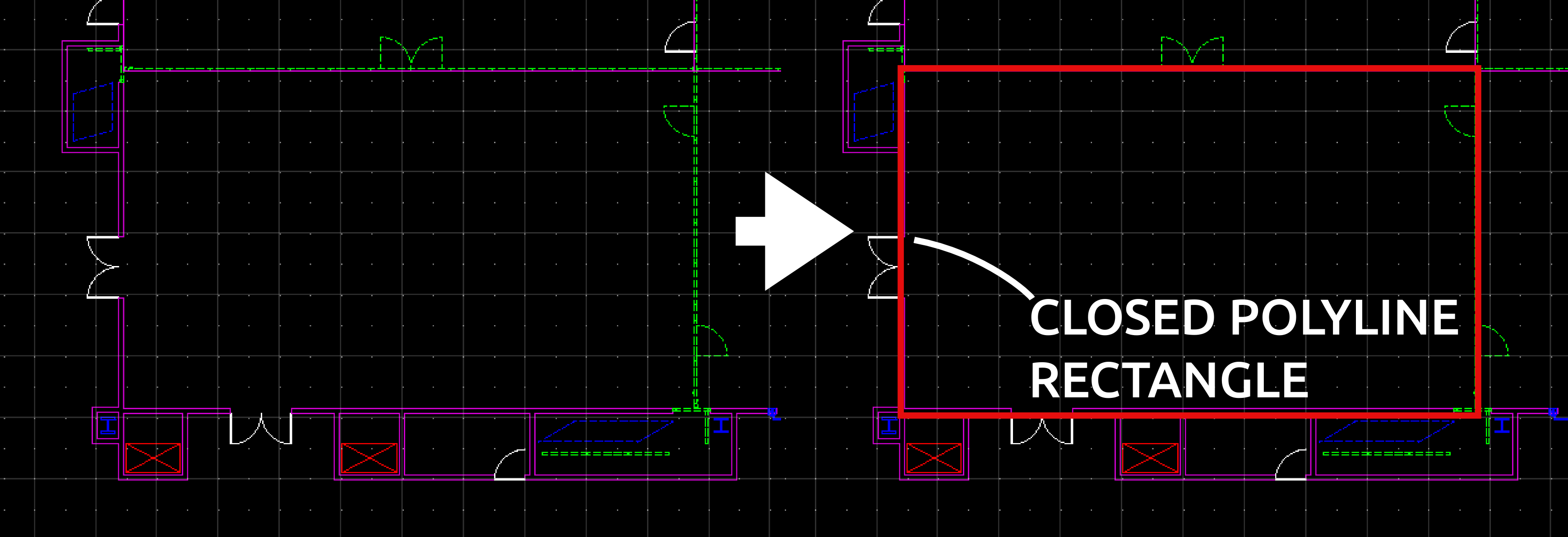
Step 3: Draw Geometries
For each feature that should be shown on the map, a geometry is needed. Therefore, please draw a closed polyline, such as a rectangle, around every feature (illustrated below). You can determine if a polyline is closed by selecting it and ensuring all line segments are connected.
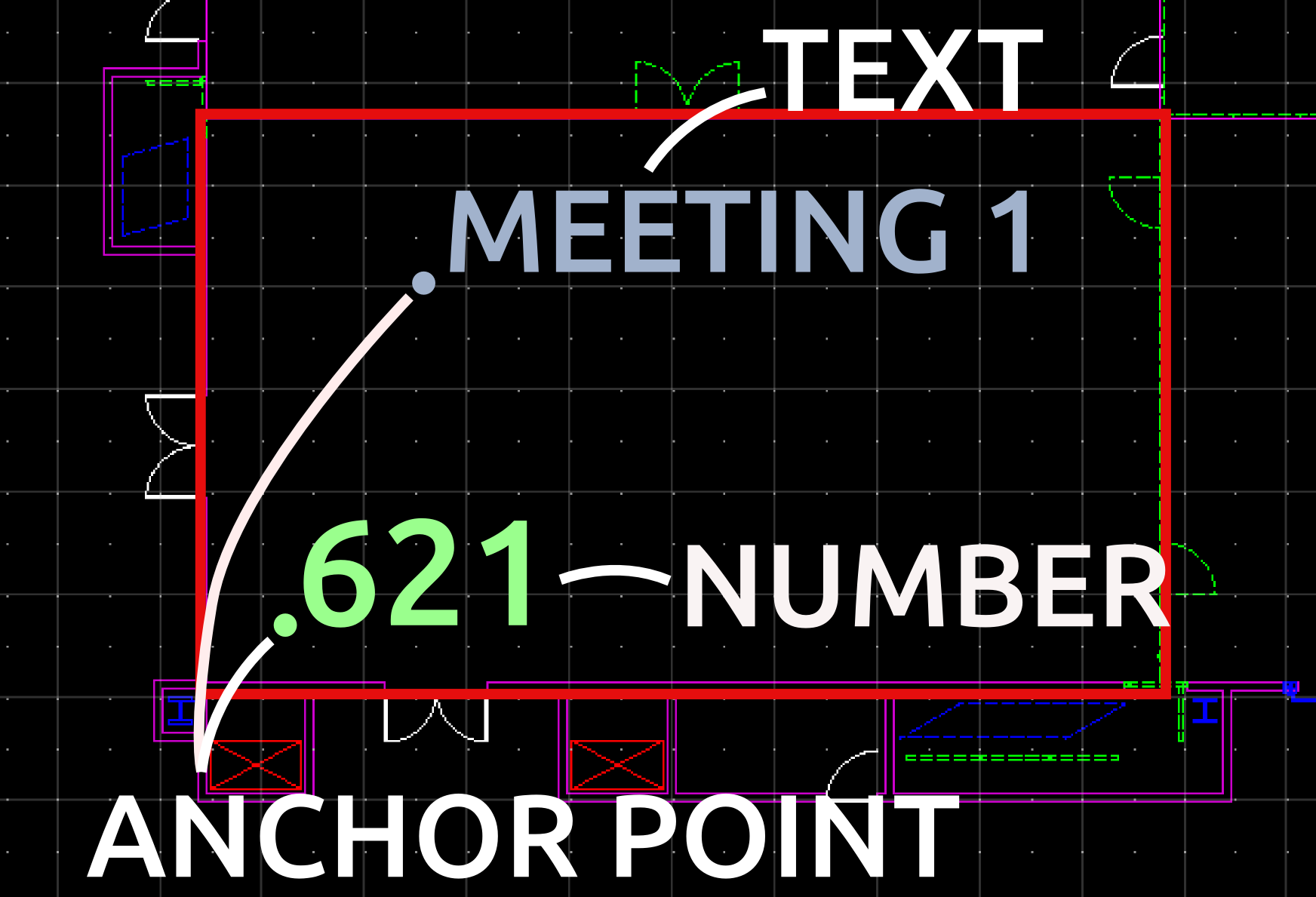
Step 4: Name/Number the geometries
Each geometry needs to be identified by a unique name or number. The name/number has to be a Text object. A Text object within a CAD file is aligned by its anchor point (illustrated below). To guarantee that the geometry and the name/number can be matched, please make sure that the anchor point of the text object lies within the geometry. On the map the name can be used as maplabel and the number as unique identifier of the geometrie.
Furthermore, line breaks and special characters are not allowed.
Step 5: Send the files to Heidelberg Mobile
We will validate your created CAD data and design your map.